This chapter describes the Motorola 68000 simulator (Sim68000) and assembler (68kasm) included in the BSVC distribution.
The Motorola 68000 simulator included in the BSVC distribution simulates the 68000 at the software level. This means the simulator does not understand what goes on in the 68000 at the hardware level. Instead the simulator performs a set of actions for each instruction that gives the same result.
NotesThe 68000 simulator provides two devices that can be attached to the microprocessor. These devices are the M68681 Dual UART and RAM (the Windows 95 version does not support the DUART at this time). Each of these devices is described below.
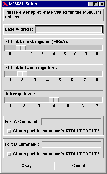
M68681 Dual UART DeviceThe M68681 Dual Universal Asynchronous Receiver/Transmitter (DUART) device is modeled after the Motorola MC68681 DUART. The dialog box shown in Figure 3-1 allows you to customize the M68681 device when it is attached to the 68000.

Using this dialog you can select the:
The M68681 device supports the following features:
Each communication port comprises a full-duplex universal asynchronous receiver/transmitter (UART). The baud rate for each receiver and each transmitter can be independently selected using the built in baud rate generator.
The transmitter accepts parallel data from the CPU and sends it to the Unix process connected to the port. The receiver accepts data from the Unix process connected to the port and transfers it to the CPU during read operations. If no process is connected to the port there will never be any data to read and writes will send data to that giant-bit-bucket-in-the-sky.
Programming and Register DescriptionThe operation of the DUART is programmed by writing control words into the appropriate registers. Operational feedback is provided by the status registers, which can be read by the CPU. The DUART's register addresses are described in Table 3-1.
TABLE 3-1 Register Addressing
|
|
|
|
|
|
|
|
|
|
|
| Mode Register A (MR1A, MR2A) | Mode Register A (MR1A, MR2A) |
|
|
|
|
| Status Register A (SRA) | Clock Select Register A (CSRA) |
|
|
|
|
| Do not access | Command Register A (CRA) |
|
|
|
|
| Receiver Buffer A (RBA) | Transmitter Buffer A (TBA) |
|
|
|
|
| Not implemented | Auxiliary Control Register (ACR) |
|
|
|
|
| Interrupt Status Register (ISR) | Interrupt Mask Register (IMR) |
|
|
|
|
| Not implemented | Not implemented |
|
|
|
|
| Not implemented | Not implemented |
|
|
|
|
| Mode Register B (MR1B, MR2B) | Mode Register B (MR1B, MR2B) |
|
|
|
|
| Status Register B (SRB) | Clock Select Register B (CSRB) |
|
|
|
|
| Do not access | Command Register B (CRB) |
|
|
|
|
| Receiver Buffer B (RBB) | Transmitter Buffer B (TBB) |
|
|
|
|
| Interrupt Vector Register (IVR) | Interrupt Vector Register (IVR) |
|
|
|
|
| Not implemented | Not implemented |
|
|
|
|
| Not implemented | Not implemented |
|
|
|
|
| Not implemented | Not implemented |
Mode registers 1 and 2 of each port are accessed through independent pointers. The pointer is set to registers MR1A and MR1B by a system reset or issuing a "reset pointer" command via the corresponding command register. Any read or write of the mode register while the pointer is at MR1A or MR1B switches the pointer to MR2A or MR2B. Subsequent accesses will address MR2A or MR2B unless the pointer is reset to MR1A or MR1B.
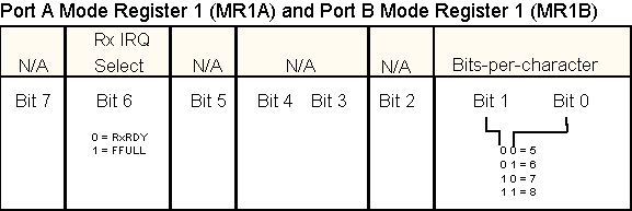
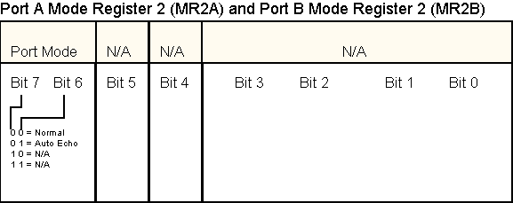
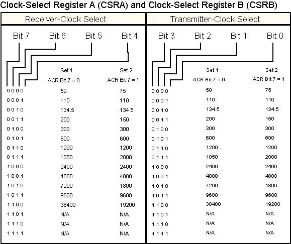
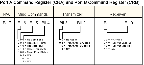
Mode, command, clock select, and status registers are duplicated for each port to provide independent operation and control. Refer to the register bit formats in Table 3-2.
For information on programming the M68681 you should consult a programmer's guide to the Motorola MC68681 DUART.
TABLE 3-2 Register Bit Formats


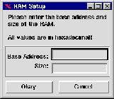
The RAM device allows you to attach a specified amount of memory to the 68000. When the RAM device is attached to the simulator, using the Edit Setup option, the dialog shown in Figure 3-2 is displayed. This dialog allows you to enter the base address and size of the RAM module. Both of these values are in hexadecimal.
The 68000 assembler is similar to many UNIX system compilers and assemblers. The assembler accepts files with the following line layout:
LABEL OPCODE OPERANDS COMMENTS
The LABEL field is optional, but if used it must start in the first column of the line. Fields are separated by spaces or tabs. An example assembly language file is shown in Figure 3-3.
           ORG        $2000        Start at location 2000 Hex
  START    CLR.W      SUM          Clear variable SUM
           MOVE.W     COUNT,D0     Load COUNT value
  LOOP     ADD.W      D0,SUM       Add D0 to SUM
           SUB.W      #1,D0        Decrement counter
           BNE        LOOP         Loop if counter not zero
           BREAK                   Tell the simulator to BREAK if running
  SUM      DS.W       1            Reserve one word for SUM
  COUNT    DC.W       25           Initial value for COUNT
Once an assembly language file has been created it can be assembled. The assembler will indicate if any syntax errors were found. If no errors were encountered the assembler creates an object file in Motorola S-Record format with a .h68 suffix. If errors were found, to get a better idea of the errors assemble the file using the "-l" option. This option tells the assembler to produce a listing file with a .lis suffix in addition to the .h68 file. The listing file can be used to find syntax errors as-well-as logic errors while executing the program.
Once the file has been assembled with no errors, the object file can be loaded into the simulator for execution. The listing file can also be loaded into BSVC's Program Listing window to facilitate debugging.
The Motorola 68000 simulator was developed by Bradford W. Mott at North Carolina State University. The simulator is loosely based on the 68000 simulator written by Jay Lloyd at NCSU.
The Motorola 68000 assembler was developed by Paul McKee at NCSU.
If you have questions about the Motorola 68000 Simulator contact:
Bradford W. Mott
bwmott@eos.ncsu.edu
This document was produced using an evaluation version of HTML Transit