See Practical serial communication


BASIC Stamp

A variety of products from Parallax. We use the BS2-IC (we have 5), we also have one SX.

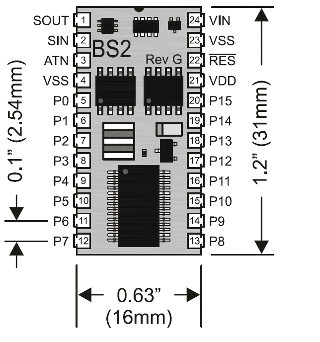
Pin layout

Pins 1-4: (serial) programming

ATN=attention

Pins 5-20: data

Pin 21: stable 5V (CMOS VDD), output if there is something on pin 24, otherwise input

Pin 22: connect ground for reset

Pin 23, 4: Ground (CMOS VSS)

Pin 24: input voltage, will be converted to 5V by the Stamp on pin 21
 

Stamp major components

See Module Schematic


The programming cable

DSR and RTS are connected for automatic port detection. The Stamp software will scan the serial ports and look for such connectors.


PBASIC

Download BASIC Stamp Editor

' {$STAMP BS2}
' {$PBASIC 2.5}

delay CON 1000
myPin PIN 8
OUTPUT myPin
bla VAR Word

start:

TOGGLE myPin
PAUSE delay
bla=bla+1
DEBUG DEC bla, CR
GOTO start

  • stamp Identify Ctrl-I
  • Syntax check Ctrl-T
  • Run Ctrl-R
  • directives
  • constants
  • PIN constants (don't use CON for pins, they are not constants!)
  • variable VAR Type
  • pin direction (INPUT, OUTPUT, REVERSE)
  • digital output (HIGH, LOW, TOGGLE)
  • PAUSE milliseconds
  • DEBUG format variable Comma CR
    • same as SEROUT 16, $4054, {...}
    • Alt-1 to bring back your debug window
    • Format DEC, BIN, HEX
  • GOTO label
  • Memory Map Ctrl-M

Variable types

Array of the above

Modifiers

Accessing the RAM as predefined values

Literals

% binary

$ hexadecimal

Operators and Math


Digital output


Digital input

Analog input

Driving a servo


Categories of PBASIC statements