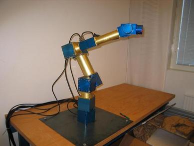
In order to study teleoperation in a highly dynamic context, we have constructed a fast robotic manipulator. This page will give a closer presentation of the technical specifications and implementation issues of the platform.
The arm has been designed in order to use in experiments for teleoperated ball-catching. Therefore, the main goal of the mechanical design has been to cover a large enough area in short enough time to be able to do this.
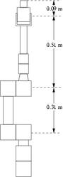
A 'large enough area' has been defined as a 0.6 m by 0.6 m window, based on the precision of a normal underhand ball toss. A 'short enough time' has been defined as 0.5 s, based on the flight time of ballistic objects and the reaction times of the teleoperated system. In simulation our robot arm can, if started in the middle of the operating window, reach any point therein within 0.3 s, which should be fast enough with ample margin. In actual experiments, simulated performance has only been verified for a very limited amount of movements, but the actual system shows good promise to perform within 10% of simulation.
The requirements are met by using a well-known and tested kinematic structure and varying different parameters until optimal performance was reached. The kinematic structure is basically the same as that of a Unimate Puma560, or very similar to many industrial models. Using a standard kinematic form means that there are readily available solutions of inverse kinematics and dynamics. The main difference between our robot and most industrial robots is merely the power-to-mass ratio, as we have almost 5 kW to move approximately 10 kg.
Construction details
The arm is constructed with Amtec PowerCubes. These are self-contained actuators with onboard controllers that can be controlled over a CAN bus. Although the modules documentation claims that they support 1 Mbit/s bus speeds, allowing approximately 6000 messages per second over the bus, practical tests have shown that this causes an overload of the onboard CPU, so that in practice communication has to be limited to sending about 2000-3000 messages per second - which allows for 500-700 Hz control as 4 messages (send current, receive status response, poll velocity, receive velocity) are needed per control loop iteration. Apart from this, testing so far indicates that the modules perform according to specification, with regard to speed, power and precision. The control loop is currently running at 625 Hz.
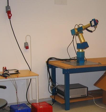
The arm is mounted on a sturdy (rated for loads up to 1000 kg) industrial table that has been bolted to the lab wall. The table has in turn been reinforced with a 6 mm steel plate. This has so far proved to be a rigid enough mounting.
Power to the arm is supplied via 3 Cosel PBA-1500F units that supply each of the PR 110 units with 48 V up to 30 A for actuation, and one Cosel PBA-1000F unit that supplies 24 V up to 45 A for control electronics and actuation of the PR 070 and PW 070 units. Here is a circuit diagram for the power source.
The following parts have been used for the arm itself:
This clip shows one of the first tests of high speed motion with the manipulator, moving 60 cm vertically from standstill to standstill in approx 0.5 s.
The following clips show the first prototype implementations of autonomous ballcatching. Catch rate is at present approximately 90% for benevolent throws.
The control frequency depends on the velocity measuring strategy. If velocity is interpolated from position readings, only half the number of messages are needed. However, the uncertainty in the time-stamps of the position readings means that the accuracy deteriorates considerably. The control frequency is expected to improve as the control system is more finely tuned.
Publications
Christian Smith and Henrik I Christensen. A Minimum Jerk Predictor for Teleoperation with Variable Time Delay
(accepted for) IEEE/RSJ International Conference on Intelligent Robots and Systems (IROS 2009). pp XXX-XXX, 2009 bibTeXabstract
Christian Smith and Henrik I Christensen. Wiimote Robot Control Using Human Motion Models
(accepted for) IEEE International Conference on Intelligent Robots and Systems(IROS 2009). pp XXX-XXX bibTeXabstract
Christian Smith and Henrik I Christensen. Constructing a High Performance Robot from Commercially Available Parts
(Accepted) IEEE/RAS Robotics and Automation Magazine (2009) bibTeXabstract
Mattias Bratt, Christian Smith and Henrik I Christensen. Minimum Jerk Based Prediction of User Actions for a Ball Catching Task
IEEE/RSJ International Conference on Intelligent Robots and Systems (IROS 2007), pp. 2710-2716, 2007
bibTeXabstract
Christian Smith and Henrik I Christensen. Using COTS to Construct a High Performance Robot Arm
IEEE International Conference on Robots and Automation (ICRA 2007). pp 4056-4063
bibTeXabstractpdf
Mattias Bratt, Christian Smith and Henrik I Christensen. Design of a Control Strategy for Teleoperation of a Platform with Significant Dynamics
IEEE/RSJ International Conference on Intelligent Robots and Systems (IROS 2006). pp 1700-1705, 2006
bibTeXabstractpdf